Introduction
The Pseudo-3D tunnel is a well known effect, which was commonly seen in old demos. It uses a very simple mapping trick to create the illusion of movement in 3d space. The algorithm is very easy to understand and implement, and only requires basic trigonometry knowledge.
Theory
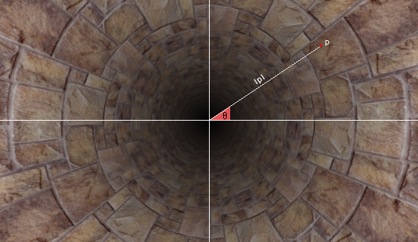
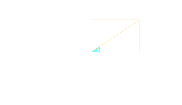
An easy way to visualize how the algorithm works, is to imagine a texture projected on the surface of an axis aligned finite cylinder. This can be achieved by mapping the texture's u coordinate around the cylinder's edge with the use of the edge's spherical theta coordinate, and the texture's v coordinate across the cylinder's height using the reciprocal distance. Now imagine that the cylinder we described is a monocular and you are looking through it. The following image illustrates what you would be seeing.
The coordinates are calculated as follows:
Note that all the calculations are done in 2d space. Animating is even simpler as all that needs to be done is to add a scrolling offset to the resulting uv coordinates. It is worth mentioning that in the original version, the uv coordinates where precalculated and look-up tables were used to minimize the computational cost and optimize performance. However, modern hardware can execute the required operations in real time, at virtually zero cost.
Implementation
Below is an example implementation in a GLSL fragment shader.
#ifdef GL_ES
precision highp float;
#endif

// Notes
// p: Screen coordinates in [-a,a]x[-1,1] space (aspect corrected).
// t: The texture uv coordinates.
// u: The angle between the positive x axis and p.
// v: The inverse distance of p from the axis origin.
// s: Scrolling offset to create the illusion of movement.
// z: Texture uv scale factor.
// m: Brightness scale factor.

void main(void)
{
	vec2  p = (2. * gl_FragCoord.xy / iResolution.xy - 1.)
     	        * vec2(iResolution.x / iResolution.y,1.);
	vec2  t = vec2(atan(p.x, p.y) / 3.1416, 1. / length(p));
	vec2  s = iGlobalTime * vec2(.1, 1);
	vec2  z = vec2(3, 1);
	float m = t.y + .5;

	gl_FragColor = vec4(texture2D(iChannel0, t * z + s).xyz / m, 1);
}
The following examples perform some additional calculations in image space to achieve more complex visuals, however, both of them use the base technique presented here.