The technique
Shadow mapping was introduced by Lance Williams in 1978 and is still the most popular technique for implementing dynamic shadowing. The technique is relatively easy to understand and implement in its basic form and a wide range of extensions have been developed to improve its visual quality.
Workflow
The basic algorithm can be broken down to two passes:
- Depth map generation: The scene is rendered from the light’s point of view, capturing only the depth value for each fragment. The output of this step is called a shadow map and is stored in a depth texture, that will be sampled in the next pass.
- Shadow evaluation: The scene is rendered from the main camera’s point of view and for each fragment we use the shadow map from the previous pass to determine whether the fragment is occluded from the light’s point of view.
Rendering from the light’s point of view
In most cases, shadow maps are computed for a single directional light source that is positioned very far away from the scene. The most commonly used light source is the sun.
With the light source being that far, light rays can be considered to be travelling parallel to one another, and the shadow map can therefore be rendered using an orthographic projection.
A model-view-projection (MVP) matrix is computed to render the view. Note that the view matrix uses the inverse light direction as the eye position for its look-at calculation. The orthographic projection matrix is setup so that its bounds encompass all geometry that is visible from the camera’s point of view. In other words the “light camera’s” frustum needs to encapsulate the main camera’s frustum.
Occlusion test
In the second pass, each fragment’s position is used to evaluate whether its in shadow or not. This is done by checking if the shaded fragment is further away from the light than the distance stored in the shadow map. A fragment is essentially occluded if there is another surface in front of it when looking at the scene from the light’s point of view.
In order to do this comparison, both positions need to be in the same space.
The vertex position is transformed to the shadowmap’s space using the light MVP matrix from the first pass, with a little added twist. The matrix that was used above will produce a position in homogeneous coordinates [-1, 1]. However, in order to sample the depth texture, the coordinates need to be in the [0, 1] range. This can be easily rectified using the following calculation[2]:
\[coord_{shadow-biased} = coord_{shadow} * 0.5 + 0.5\]which in matrix form is:
mat4 matBias(0.5, 0.0, 0.0, 0.0
          ,  0.0, 0.5, 0.0, 0.0
          ,  0.0, 0.0, 0.5, 0.0
          ,  0.5, 0.5, 0.5, 1.0);
matMVP = matBias * matLightMVP;
Multiplying the transformed vertex by this matrix in the vertex shader calculates its position in normalised light space. This is then interpolated in the fragment shader, and the z value is used to compare against the value stored in the shadow map, to determine if the fragment is in shadow or not.
float shadowmap_depth = sample(shadow_map, coord.xy).z;
bool is_occluded = shadowmap_depth < coord.z;
Limitations
One of the drawbacks of conventional shadow mapping is that it is not possible to pre-filter the shadow map, as this would generate inaccurate depth values for the geometry represented in the map.
The most common artefacts associated with shadow mapping are discussed below.
Aliasing
Due to the discrete nature of the shadow map, shadow edges will exhibit a jagged look which essentially matches the boundaries of the sampled pixels.
Shadow Acne

The shadow map stores a discrete representation of scene depth from the point of view of the light source, and it is rendered using a fixed resolution. When the scene is then rendered from the camera’s vantage point, the surfaces that are not in shadow will have a distance value very close to the one stored in the shadow map, which leads to z fighting.
Furthermore, the discrete area that each pixel in the shadow map represents does not map to the same area in our final render, and in fact the size of that area will vary depending on the main camera’s view angle. This, combined with the z fighting issue described above, is why it’s common to see the characteristic blind and/or Moivre patterns when this aliasing artefact occurs.

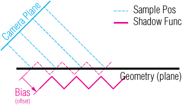
One way to reduce the effect of this artefact is to allow for some margin of error. This can be achieved with offseting the shaded fragment by an epsilon value. The specific epsilon value might need to be adjusted depending on the content of the scene.
float bias = 1e-4;
float shadowmap_depth = sample(shadow_map, coord.xy).z;
bool is_occluded = shadowmap_depth < (coord.z - bias);
While this is more or less effective for planar surfaces, it can’t solve the issue entirely for geometry. an alternative technique is to scale the bias value, based on the surface slope.
float bias = 1e-4;
float costheta = dot(n, l);
bias *= tan(acos(costheta));
bias = clamp(bias, 0.0, 0.01);
Another approach is to leverage built-in face culling, by rendering only the back faces of geometry on the shadow mapping pass, The depth values in the shadow map will then accomodate for that error margin that is otherwise introduced with the bias value above. This approach imposes additional requirements on the topology of the geometry in the scene and does not work well with thin surfaces (eg. thin walls, leaves, etc).
This is the corrected output:

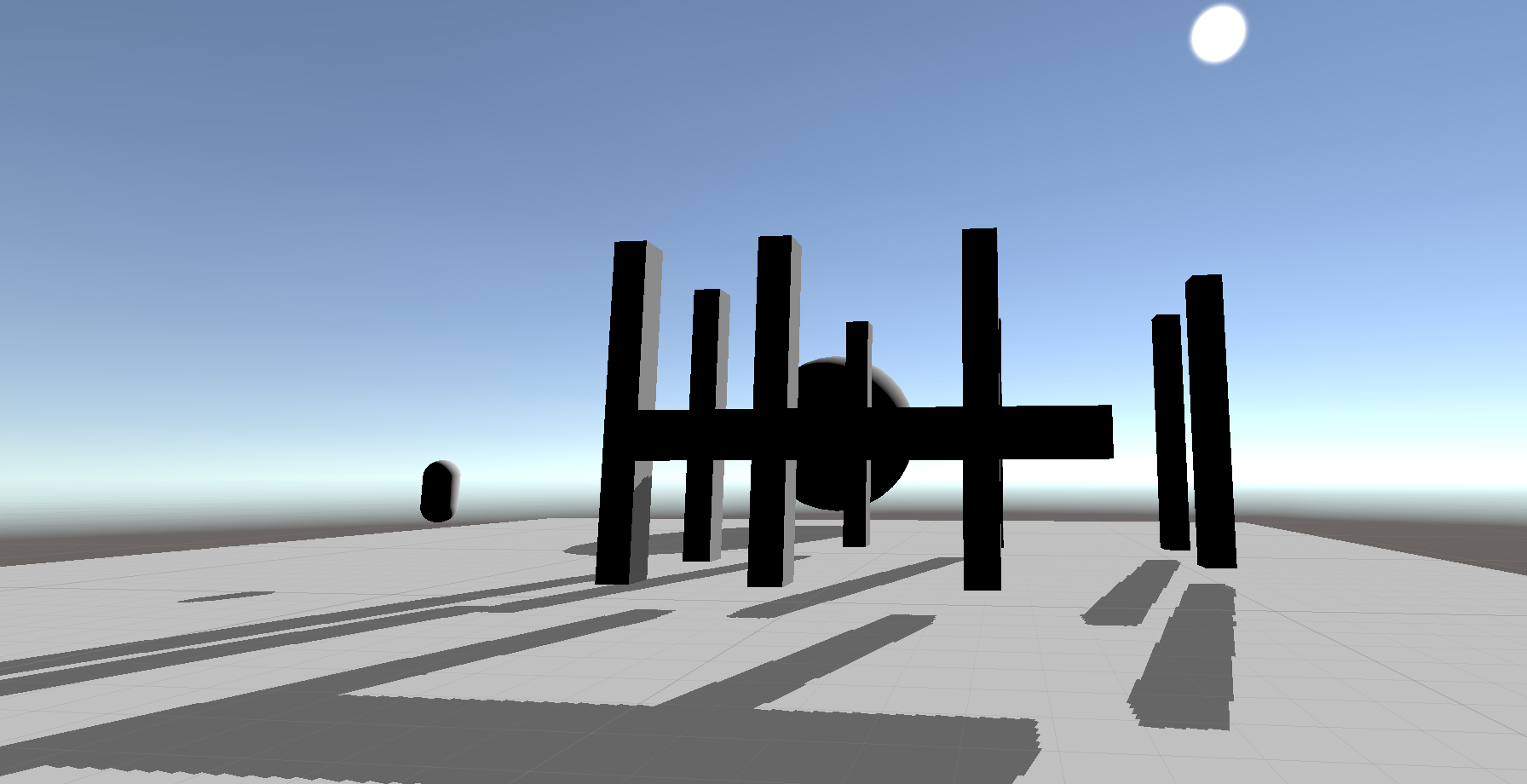
Peter Panning
As discussed above, shadow acne artifacts can be resolved by allowing for some error of margin. The specific bias value to use is dependent on the topology and scale of the geometry in the scene. If the bias is too large, another artefact called ‘Peter panning’ is observed, where the shadows are offset and objects appear to be floating. This is demonstrated below.
Shimmering
In a typical scenario, as discussed above, the “light camera’s” frustum is dynamically updated and resized to incorporate the rotated frustum of the main camera. This practically means that the size of the geometry in the shadow map constantly changes. Subsequently, the size of the area covered by each individual pixel in the shadow map is changing rapidly as well. As the camera moves and rotates high frequency changes will occur on shadow edges as each pixel in the shadow map will represent an area of varying size from frame to frame. This is refered to as shimmering.
A solution to this is to encapsulate the main camera frustum within a sphere and then calculate the bounds of the light camera’s orthographic projection based on that sphere. As the sphere is rotation invariant it will account for all possible orientations of the main camera’s frustum and keep the size of the light camera’s frustum constant at the expense of underutilizing depth map real estate.
Implementation
I’ve put together a minimal project in Unity that implements the above. The full source code is available at github: 4rknova/unity.experiment.shadowmapping